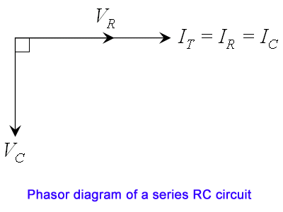
Rc Series Circuit Voltage Phasor Diagram
Series rlc circuit (circuit & phasor diagram) Circuit rlc diagram phasor series voltage current phase between inductor capacitor relationship vector leads electrical4u impedance simple civil gif remembering Circuit rc diagram phasor series
Phasor Diagram Of Rl Circuit / Solved V Figure 7 7 Phasor Diagrams Of
Phasor diagram of rl circuit / solved v figure 7 7 phasor diagrams of Solved part 3pe: series rc circuit. consider the circuit Jackng c. h. blog: series rc circuit (rev: 1.41)
Why is the inductive reactance or capacitive reactance phasor on the
Phasor circuit rlc series diagram voltage current ac power draw phase impedance triangle reactive angle phasors physics lagging length questionsCircuit phasor series rlc inductive reactance diagram voltage capacitive parallel analysis impedance vector reference power source axis electrical imaginary why Circuit rc series vr phasor consider chegg solved shown figure calculate 3pe part transcribed problem text been show hasWhat is rlc series circuit?.
Phasor circuit rl .


Phasor Diagram Of Rl Circuit / Solved V Figure 7 7 Phasor Diagrams Of

Why is the inductive reactance or capacitive reactance phasor on the

What is RLC Series Circuit? - Phasor Diagram & Impedance Triangle

Solved Part 3PE: Series RC circuit. Consider the circuit | Chegg.com

JackNg C. H. Blog: Series RC circuit (Rev: 1.41)